Aries: An LSI Macro-Block for DSP Applications
![[PREV]](PIC/back.gif)
![[TOC]](PIC/toc.gif)
![[NEXT]](PIC/fwd.gif)
![[PREV]](PIC/back.gif)
![[TOC]](PIC/toc.gif)
![[NEXT]](PIC/fwd.gif)
The final layout of the Aries architecture can be seen in Figure 7.1. The layout occupies an area of 1.26mm x 1.13mm (1.425mm^2). Please note how closely this final layout conforms to the initial floorplan given in Figure 4.3. The lower part of the layout comprises of the two shift register blocks. the space between these blocks is reserved for clock buffers and SRAM read/write circuitry. The two Dual-Port SRAM blocks dictate much of the circuits size. Three stages of adders are placed in between these rows.
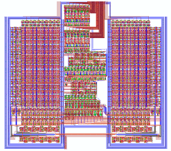
![[ZOOM]](PIC/mag.gif) Figure 7.1: Final layout of the Aries architecture.
Figure 7.1: Final layout of the Aries architecture.
![[TOC]](PIC/toc.gif)
![[TOP]](PIC/up.gif)
Aries has two main operation modes: Initialization Mode and Computation Mode. The operation of Aries relies on pre-computed co-efficients that comprise the filtering kernel. Prior to computation mode these values have to be loaded into the RAM blocks. The Initialization Mode serves this purpose. The Computation Mode is the general operation mode where at each clock cycle a new data is read and the result in the current pipeline is send to the output. The Computation Mode can be interrupted by a Initialization Mode to update the co-efficients.
![[TOC]](PIC/toc.gif)
![[TOP]](PIC/up.gif)
An Aries block is expected to operate mostly in the Computation Mode. The Initialization Mode is necessary to load the values of the co-efficients after the chip has been powered-on. The same mode can be used to update the values of co-efficients during normal operation. Intelligent adaptive filtering algorithms fine tune the coefficients during operation to obtain better results. The process of updating the coefficients will cause an interruption of processing, for some signals like images this would not be a real problem as most of the image signals have a blanking time where no actual signal is present. Figure 7.2 shows the general block diagram during the Initialization Mode
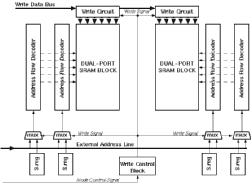
![[ZOOM]](PIC/mag.gif) Figure 7.2: General block diagram during the Initialization Mode.
Figure 7.2: General block diagram during the Initialization Mode.
A single bit controls the mode of operation. The RAM blocks within Aries require an idle state between write and requests. The single bit drives the aforementioned (see Figure 5.13) RAM control block. This control block inserts an idle state after the first clock (the fast clock is used within the RAM blocks). All four RAM blocks within Aries need to have exactly the same information. As two dual port RAM blocks are used only two blocks need to be written. Once the write signal has been issued by the control block, the Multiplexers at the end of the shift registers select the same external address lines. The total control for the write operation has now been transfered to an external source.
The write operation is not clocked, any value in the write bus is written to the row addressed by the address lines. The circuit ensures that the total decoding and writing will take less than 10 ns. After all the co-efficients have been loaded the mode control bit can be changed to the Computation Mode value of logic "0". Figure 7.3 shows the timing of the Initialization Mode.
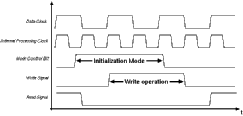
![[ZOOM]](PIC/mag.gif) Figure 7.3: Timing of the Initialization Mode.
Figure 7.3: Timing of the Initialization Mode.
A simple external counter can be used to update all the coefficients within the Aries block.
![[TOC]](PIC/toc.gif)
![[TOP]](PIC/up.gif)
For most of the time the Aries block is expected to run in the Computation Mode. This is the mode that actually performs the convolution. Only a few control signals have to be set for proper operation:
Aries is a fully pipelined design which causes a certain latency in the output (depending on the adder tree and the mode selections the latency may change). It must be noted that all five data registers must have valid values before the first value can be calculated. This initial value problem can be addressed in which the first value is fed five times to fill up all the registers with a known value.
Another important issue is that overflow within the internal adders is not propagated to the output. Overflows within the addition blocks (especially when two's complement number representation is used) can cause erroneous output. An overflow flag would not be of much use as there is no practical way to re-calculate the whole value (the pipeline will contain partial results for subsequent operations, that has to be cleared first). For fixed co-efficient applications the co-efficients can be chosen accordingly, to ensure that there is no overflow within the block. For adaptive applications the co-efficient dynamics can be kept within certain bounds (notice that the limitations will depend on the number representation system and in any case will cause only slight restrictions on the co-efficient dynamics).
![[TOC]](PIC/toc.gif)
![[TOP]](PIC/up.gif)
Aries is designed as a basic building block to be used in the design of higher order 1-D and 2-D signal filters. A number of identical Aries blocks can be used to generate the desired kernel size. This section documents how a number of Aries blocks can be combined to form a complete filter. As 1-D kernels can be considered as a special case of a 2-D architecture (where y=0) this section only concentrates on the design of 2-D kernel structures. Figure 7.4 shows the general structure used to combine a number of Aries blocks.
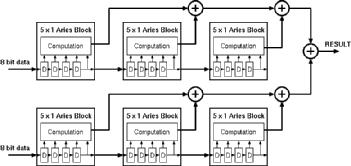
![[ZOOM]](PIC/mag.gif) Figure 7.4: General structure used to combine a number Aries Blocks.
Figure 7.4: General structure used to combine a number Aries Blocks.
Each Aries block can be used as a 5x1 filter kernel. Using an appropriate number of blocks any size of filter kernel can be realized. Scaling in the Y direction is relatively easy, as the data in every row is independent of each other, it is enough to add a new data input line and repeat the structure used for X axis alongside the row. The results of different rows have to be added at the end. Scaling on the X axis is a little more tricky. The length of the kernel along the X axis actually corresponds to the number of subsequent samples that have to be processed. This time delay is realized by the input registers in Aries. At every rising edge of the clock a new data is read and the remaining data are pushed deeper in the shift register chain. To be able to scale in the X axis this pushed data has to be transferred to the next stage. Aries uses a separate bus to transfer the outputs of the shift registers to the next stage.
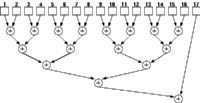
A design with n Aries blocks will generate n independent results each clock cycle. These results need to be added to form the final result. As these results are independent of each other, they can be added in any order. The final adders (see Section 6.4) within the Aries block can be used to perform this addition. Using a binary tree structure theoretically n numbers can be summed up using at most n-1 adders. As there are n Aries blocks, there are enough adders present to form a binary tree. For a binary adder tree with exactly 2^n operands it is possible to create a pipeline without any problems. Figure 7.5 shows an adder tree that adds up 17 results . Although still 16 adders are required for the operation notice that the result of block 17 is added to the combined sum of the first 16 blocks which are calculated in a four level adder tree.
![[ZOOM]](PIC/mag.gif) Figure 7.5: A binary tree adder for 17 numbers.
Figure 7.5: A binary tree adder for 17 numbers.
For a pipelined architecture this is not acceptable, as the result of the 17th block needs to wait for four adder delays. A pipeline structure would require that fouradditional delay elements be used for the result of the 17th block. This problem is solved by the output stage of Aries which is described in Section 6.3. This arrangement has two modes: one where the result is available directly and another one where the result is delayed by one pipeline stage. Both of these results can either be fed to the internal final adder or redirected to output. It can be shown that any number of operands can safely be implemented with this arrangement.
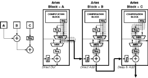
![[ZOOM]](PIC/mag.gif) Figure 7.6: Three Aries output block configured for pipelined addition, block
diagram (left) and detailed schematic (right)..
Figure 7.6: Three Aries output block configured for pipelined addition, block
diagram (left) and detailed schematic (right)..
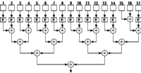
As a simple example let us consider the addition of three results, Figure 7.6 shows three Aries blocks and their output modes. Notice that all three modes are used in this arrangement. The only restriction of this methodology is that the output can only be delayed by one cycle. All these delays have to be introduced at the first level of the adder tree. To construct such an adder tree it is necessary to start from the last stage where a single adder will be used. The total number of operands are divided into two halves so that the result will be two equal numbers for even numbers and two consecutive integers for odd numbers. This process is repeated until blocks of either two or three operands are reached. Thenafter the arrangement shown in figure 7.6 is used for a three operand addition. If any three operand additions exist (which is the case when n is not a power of two), all two operand additions have to be delayed by one clock. This is accomplished by setting the delay on both of the blocks, which will pass the results through the additional pipeline register before the final adder.
![[ZOOM]](PIC/mag.gif) Figure 7.7: Fully pipelined binary tree for 17 operands using Aries blocks.
Figure 7.7: Fully pipelined binary tree for 17 operands using Aries blocks.
Figure 7.7 shows the arrangement for a pipelined 17 operand adder. On the first level there are 7 , 2 operand additions and only one 3 operand addition. As a result all of the operands of the two operand adder have to be delayed by one cycle. From the second level on it can be seen that all results can be calculated within the same clock cycle.

![[ZOOM]](PIC/mag.gif) Figure 7.8:General arrangement of 5 Aries blocks to realize a 5 x 5 filter .
Figure 7.8:General arrangement of 5 Aries blocks to realize a 5 x 5 filter .
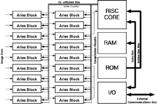
The general arrangement for a 5 x 5 filter would be like the one illustrated in Figure 7.8. Filters of any dimensions can be realized with the configuration shown. Another approach for building large filters would be to include a small RISC processor core to help programming the weights of all Aries blocks as well as add intelligent scaling algorithms for the results. The general block diagram of a large filter array that uses a RISC processor core is given in Figure 7.9.
![[ZOOM]](PIC/mag.gif) Figure 7.9: A large filter realization using Aries blocks with an embedded RISC
processor core to update weights.
Figure 7.9: A large filter realization using Aries blocks with an embedded RISC
processor core to update weights.
![[PREV]](PIC/back.gif)
![[TOC]](PIC/toc.gif)
![[TOP]](PIC/up.gif)
![[NEXT]](PIC/fwd.gif)
 KGF
KGF