


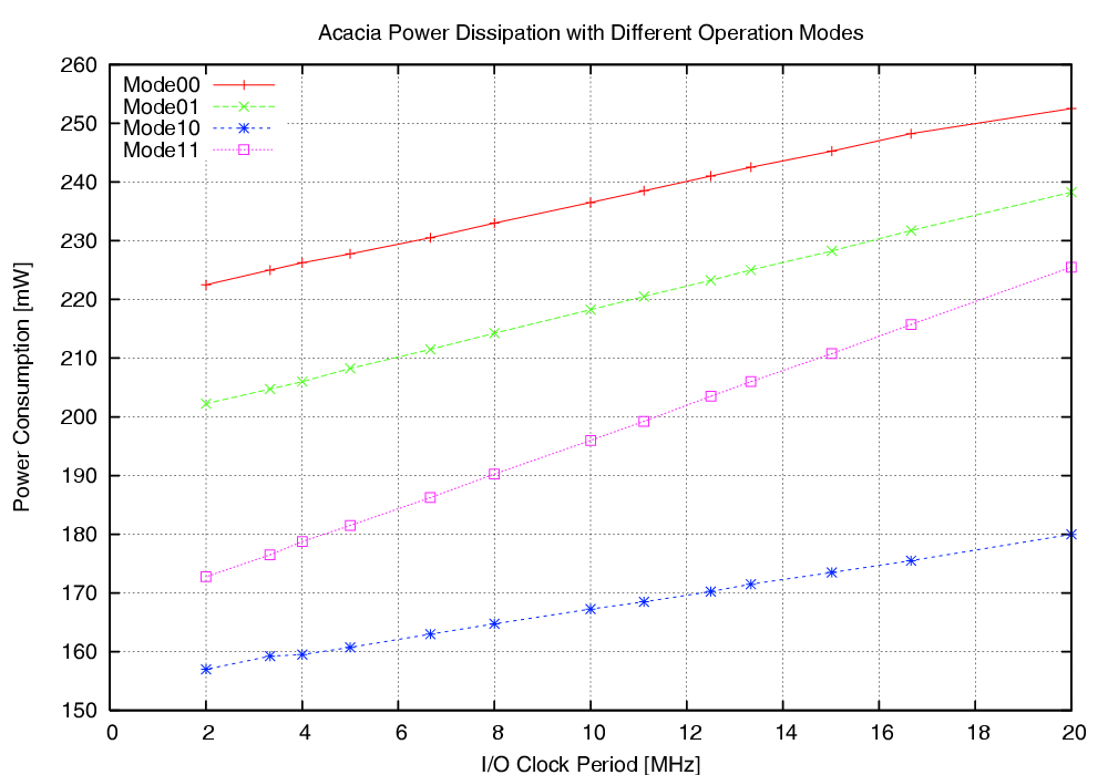
| Mode | Description | Run time [ns] | norm. |
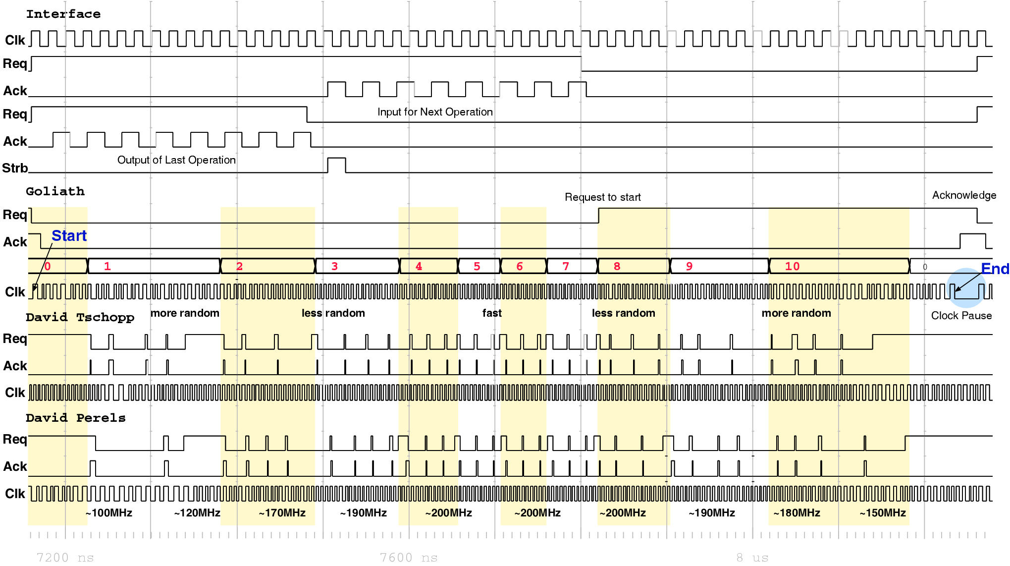
| 00 | As fast as possible | 114,400 | 1 |
| 01 | Using slightly random countermeasures | 165,320 | 1.44 |
| 10 | Using highly random countermeasures | 616,240 | 5.38 |
| 11 | Using pre-programmed policy | 203,840 | 1.78 |

| (4.1) |
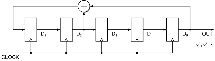
| Initial | D1 | D2 | D3 | D4 | D5 |
| P(x) | D2ÅD5 | D1 | D2 | D3 | D4 |
| P(x)2 | D1ÅD4 | D2ÅD5 | D1 | D2 | D3 |
| P(x)3 | D2ÅD3ÅD5 | D1ÅD4 | D2ÅD5 | D1 | D2 |
| P(x)4 | D1ÅD2ÅD4 | D2ÅD3ÅD5 | D1ÅD4 | D2ÅD5 | D1 |
| P(x)5 | D1ÅD2ÅD3ÅD5 | D1ÅD2ÅD4 | D2ÅD3ÅD5 | D1ÅD4 | D2ÅD5 |
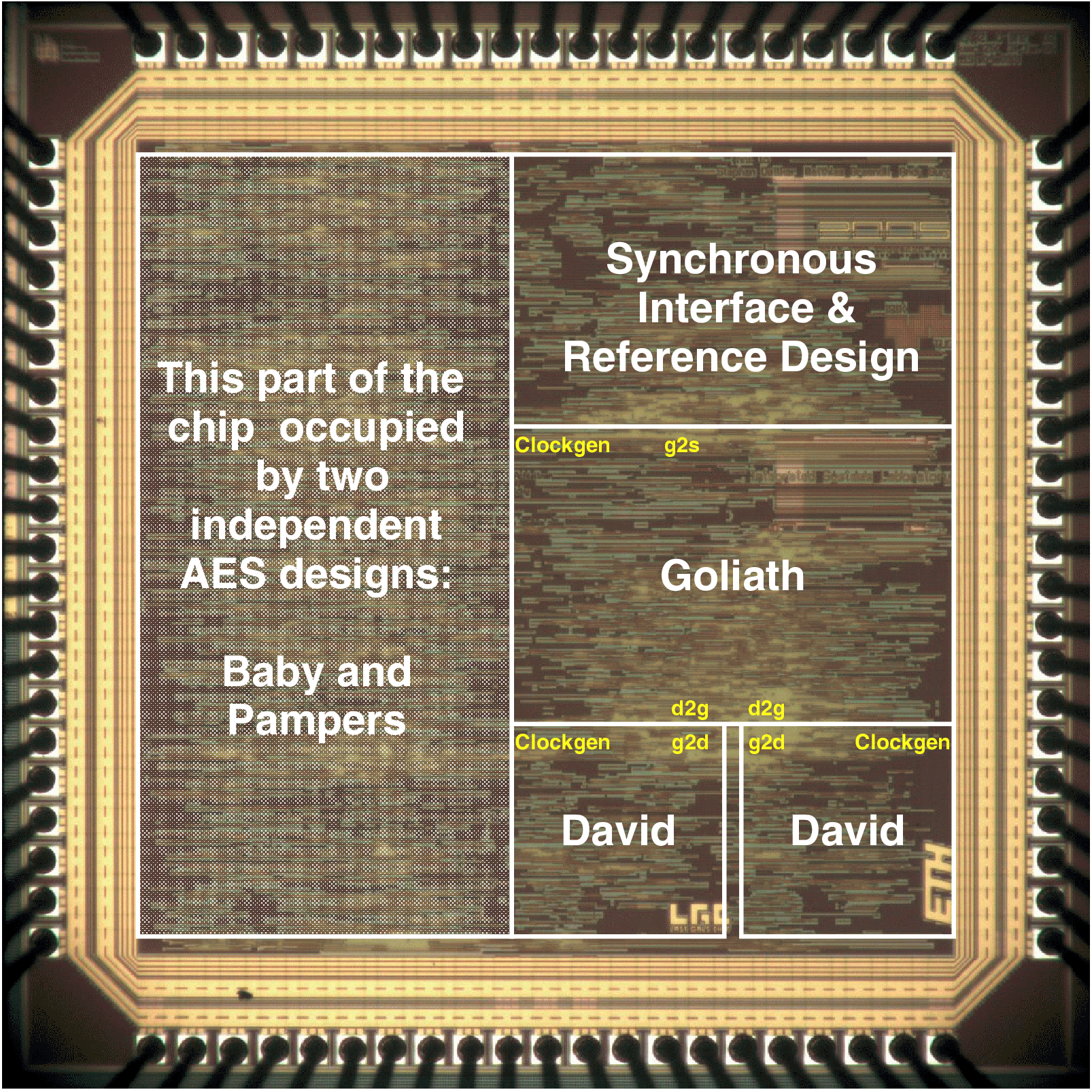
| Synchronous | GALS + DPA | |||
| Matthias | Schoggi | David | Goliath | |
| Area (m2) - LS | 93,123 | 207,031 | 183,007 | 551,194 |
| Area (m2) - ClockGen | N.A. | N.A. | 7,579 | 7,626 |
| Area (m2) - Ports | N.A. | N.A. | 6,225 | 11,412 |
| Area (m2) - TOTAL | 393,277 | 963,855 | ||
| Critical path (ns) | 5.43 | 5.84 | 3.98 | 5.27 |
| Latency (cycles) | 3 | 1 | 4 | 2 |
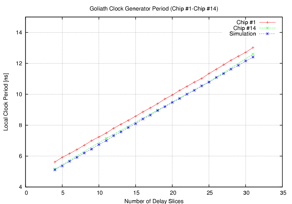
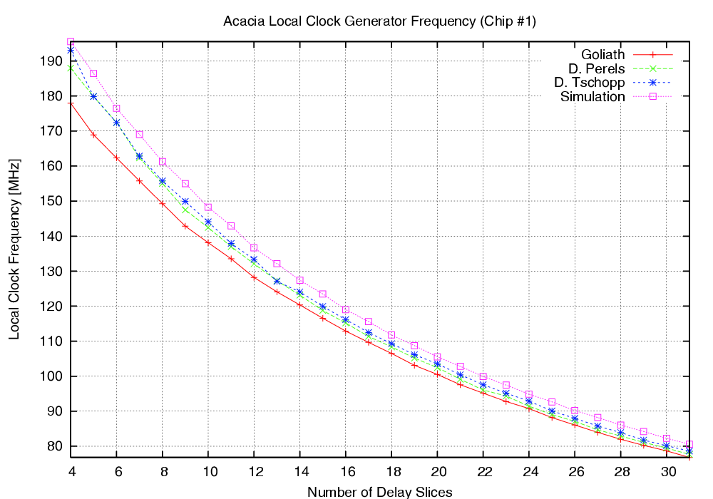
| Clock frequency (MHz) | 170.96 | 250.8 | 189.6 | |
| Encryption round (cycles) | 7 | 8 | 2 | |
| Encryption round (ns) | 40.88 | 42.38 | ||


| Mode | Clock | Number of | Max. Time | Throughput | Energy |
| [MHz] | Cycles | [ns] | [Mb/s] | [mJ/Mb] | |
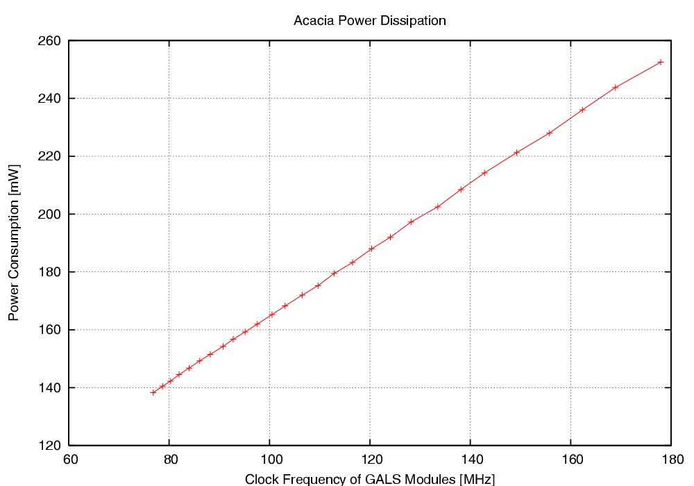
| Acacia - 00 | 50 | 36 | 720.0 | 177.7 | 1.232 |
| Acacia - 01 | 50 | 44 | 880.0 | 145.4 | 1.362 |
| Acacia - 10 | 50 | 112 | 2,440.0 | 57.1 | 2.704 |
| Acacia - 11 | 50 | 46 | 920.0 | 139.1 | 1.198 |
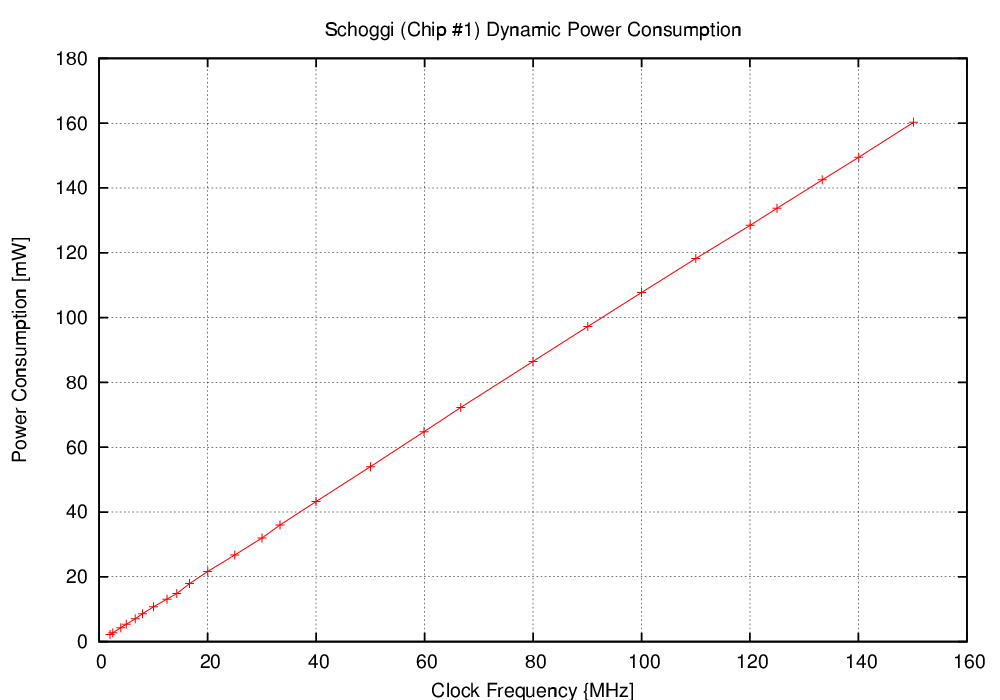
| Schoggi | 150 | 117 | 779.2 | 164.2 | 0.976 |